

My Mazda has some built-in functionality that I don’t want to lose when I replace the stereo. A Raspberry Pi and a handful of sensors should see to that.
A few months back, I finally decided my 1998 Pontiac Sunfire probably wasn’t worth throwing any more money at. Once the clutch started to go, it was time for something new. So I bought myself a shiny Mazda 3, with the i Touring package.
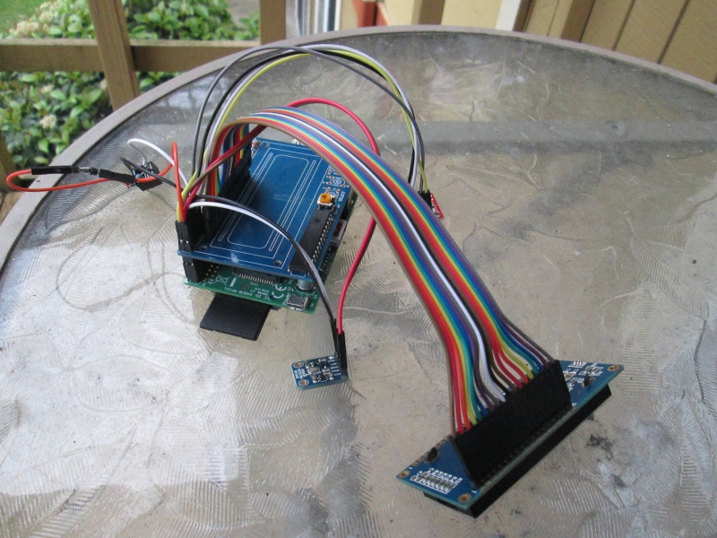
Once nice thing it has is a display for the radio that also includes a clock and a thermometer. Not being able to find reliable information as to whether the display will work at all if I replace the stock stereo, I decided to not take my chances and start working on something that will give me that functionality plus a little more. To that end, I am building the MazdaPi, a Raspberry Pi hooked up to a real-time clock, altimeter, and temperature sensor, along with a 16×2 LCD to display everything. With all the hardware hooked up, I’ve got this bit of boards and spaghetti:
Click for full size
In front we have the display, a 16×2 RGB Negative LCD from Adafruit Industries. Behind that, we have a BMP180 Barometric Pressure/Temperature/Altitude Sensor, also from Adafruit. Mostly hidden behind the ribbon cable, there is a DS1307 Real-Time Clock from Sparkfun. By itself to the left, we have a jack for the DS18D20 Temperature Sensor, also from Adafruit. I’ll show how that’s hooked up a little further down.
On a side note, I first bought the temperature sensor and an MPL3115A2-based altitude sensor from Sparkfun. For the altitude sensor, I didn’t figure out until after I’d hooked it up that the MPL3115A2 sensor will not work with the RaspPi, as the I2C interface does not support repeated start, something the MPL3115A2 requires. Additionally, while the temperature sensor is also based on the DS18D20, Sparkfun apparently has some quality-control problems. While I took it as reasonable that the wires would be black==Ground, red==V+, and white=Data, apparently sometimes the white and red are reversed on these units, and subsequently I fried mine. When I bought the replacement, I took it as reassuring that Adafruit specifically calls out what the wires will be. They also toss in the resistor required to go across V+ to Data, saving me a trip to RadioShack. Considering these resistors probably cost the distributors $.01 apiece, seems more than a little cheap that Sparkfun doesn’t do the same. Needless to say, in the future I’ll be getting everything I can from Adafruit.
I also picked up a Stacking Header and a 40-wire ribbon cable. The ribbon cable was because I had something a little different in mind for the display. This display is intended to mount to the board which, in turn, drops right onto the top of the Pi. I needed to do a little different, as the space I have available wouldn’t be large enough to hold a Pi. So, using the ribbon cable, a handful of break-away .1″ pins, and a whole lot of soldering, I have the display separated from the main PCB. Where normally the display would look like this:
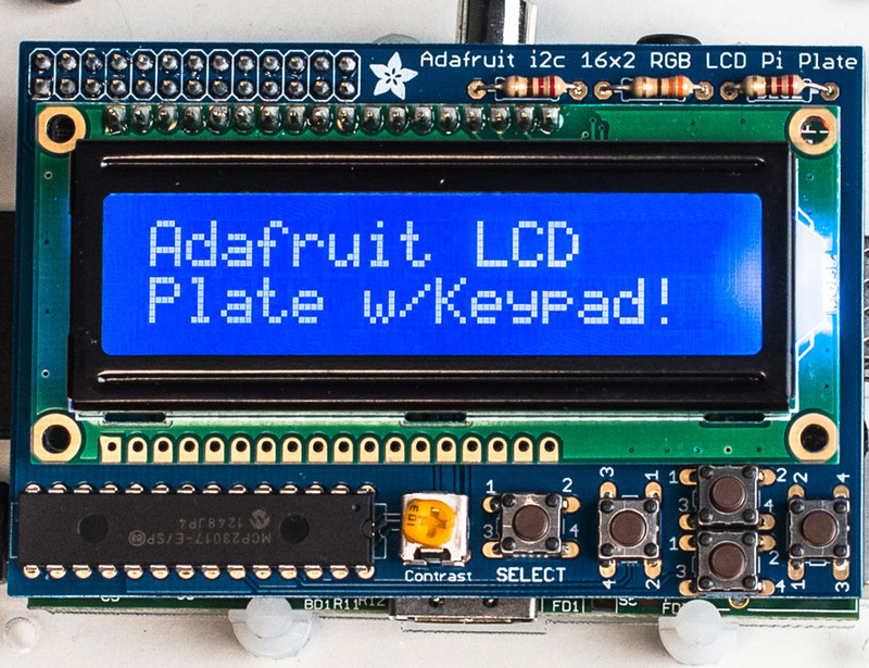
Click for full size – image courtesy of Adafruit Industries
I’ve got it on a 6″ lead that will let me mount it in the dash of my car.
My next posts will get further into the rest of the hardware. For now, I’ll call this sufficient introduction to this project.
Recent Comments